
Molded FRP Grating Mesh Geometry: A Drawing-Input Checklist
Do not select molded FRP grating from the words square mesh, rectangular mesh or micro-mesh alone. Record the visible top and bottom grid, opening and center spacing in both directions, panel depth, panel orientation, support lines, surface, cut plan and unknown fields. QY can review that drawing-input record against its available molded-FRP scope; a label, photograph or competitor catalog does not prove a QY product series, load capacity or project suitability.
Keep the catalog label separate from measured geometry
Square, rectangular and micro-mesh are useful starting labels, but they do not describe every part of a molded panel. Supplier catalogs may use the same broad label for products with different top openings, bottom grids, panel depths or molded sections. Preserve the name shown on the drawing, sample tag or previous order as a source field, then record the geometry independently.
Grating Pacific's molded-FRP page separates square, rectangular and micro-mesh product groups. The Fibergrate molded-grating details sheet also shows that products within broad grid families can have different top and bottom descriptions. These sources establish buyer terminology only; their dimensions, brands, loads, resins and compliance statements are not QY data.
The molded FRP grating product page confirms QY's published molded-FRP scope and identifies mesh size as a quotation field. It does not state that every named grid family or competitor series is available.
Use a geometry table before naming the product
The following table organizes what to record. It is not a cross-reference or selection table.
| Provisional label | Geometry to record | What the label does not prove |
|---|---|---|
| Square mesh | Top opening and center spacing in both directions; bottom grid; rib widths; panel depth | Equal strength, load, span, drainage or availability |
| Rectangular mesh | Long and short opening directions; center spacing; rib orientation; panel and support direction | Bearing direction, capacity, deflection or suitability |
| Micro-mesh or mini-mesh | Top opening pattern; bottom support grid; panel depth; transition between top and bottom geometry | One universal size, accessibility, slip resistance or compliance |
| Unknown molded grid | All measurable top, bottom, edge and section features plus photographs | Product name, resin, grade, tolerance or interchangeability |
If a value is missing, mark it `QY to review`. Do not replace it with a value copied from a visually similar catalog panel.
Photograph the top, bottom, edge and cut section
Use a full-panel view plus close photographs of the top face, bottom face and an edge. Add a ruler or controlled scale where measurement is needed. Mark the two panel directions and identify the intended walking or exposed face. If a cut sample is available, photograph the section so the panel depth, top grid and lower grid can be distinguished.
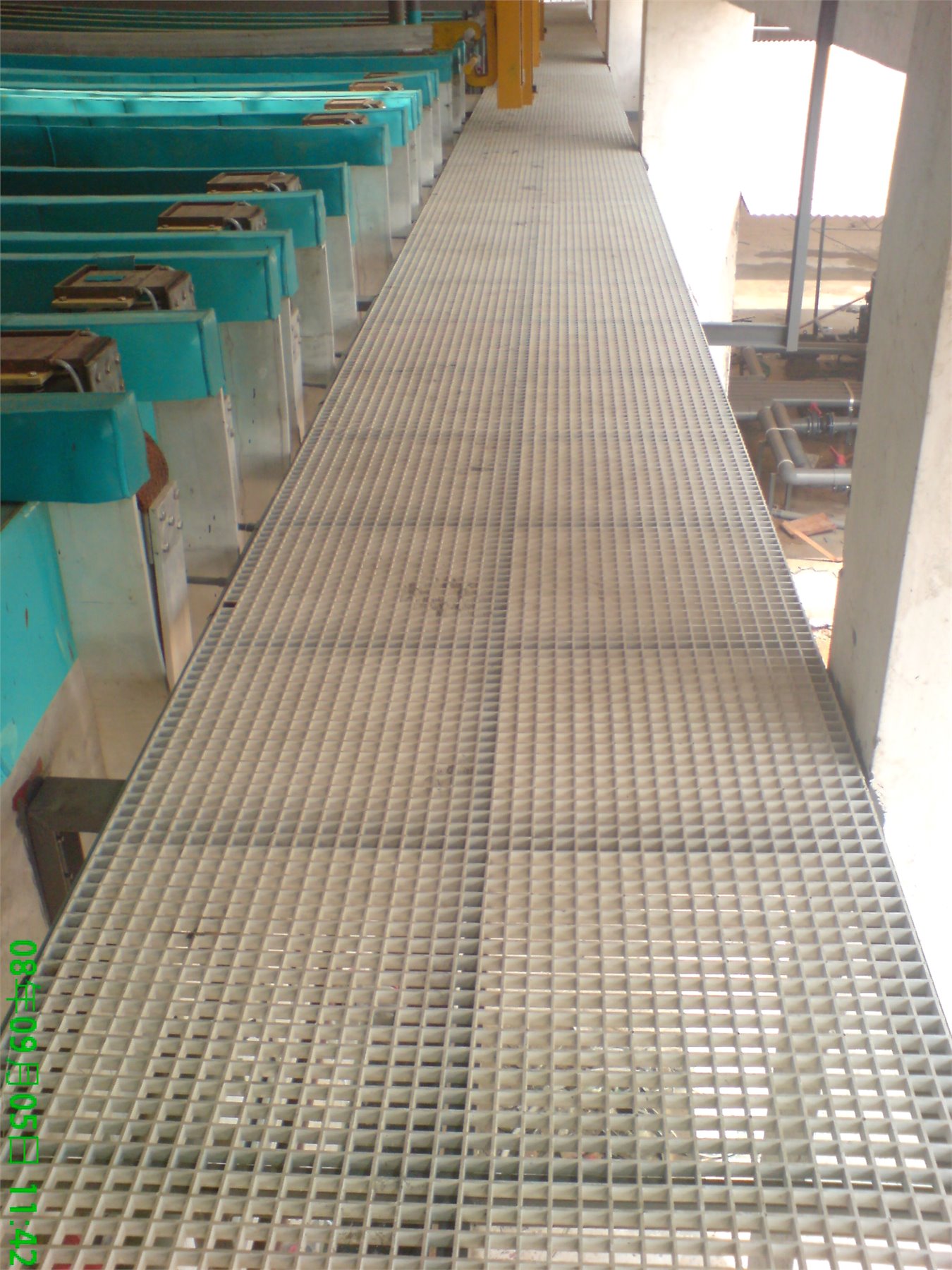
The approved QY photograph used with this draft shows a real molded-FRP walkway and visible open grid. It does not establish the grid name, opening, center spacing, depth, resin, surface, load or support design for a new inquiry.
For a cut panel, add the finished outline, openings, notches, edge distances and panel marks. The FRP cutout and edge-trim guide owns that fabrication task and should remain the detailed reference.
Draw grid direction against the support layout
The drawing should show panel length and width, the two grid directions, support lines, bearing width supplied by the project, openings, joints and the intended installation orientation. Do not infer a permitted span or load from the word square or rectangular. Capacity and deflection must be checked against the actual QY product record, panel section, support arrangement and project load basis.
Use the FRP load-table and support-span guide to keep load type, clear span, support width and deflection criteria with the correct product record. That link does not turn the present geometry checklist into structural approval.
Separate mesh geometry from resin and surface decisions
Mesh geometry does not define resin system, color, top surface, slip performance, chemical suitability, fire performance or UV behavior. Record the requested resin or exposure conditions as separate buyer inputs. Likewise, state whether the visible surface is concave, gritted, smooth or covered only when it is documented; do not quantify slip resistance from appearance.
Also keep clips, panel-to-panel joints, cut-edge sealing and installation responsibility separate from the mesh label. The purchaser or responsible designer must approve support design, loading, accessibility, opening limits, slip requirements and local code applicability.
Send one controlled mesh-geometry package
For quotation review, send the source label, top/bottom/edge photographs, opening and center spacing in both directions, panel depth, panel size, orientation, support layout, surface, resin or exposure request, cut drawing, quantity, packing and every unknown field. QY must confirm the applicable product terminology and availability case by case.
Send the controlled drawing-input package through the contact page. Do not ask QY to quote from the words micro-mesh, square mesh or rectangular mesh without the geometry and project inputs, and do not treat a third-party load table or certification as QY evidence.
Related links
Related products and RFQ guides
- FRP grating productsOpen the related product family section.
- FRP grating topic entryFRP grating family page for molded FRP grating, trench covers, car wash grating, tree grates and wet or corrosive access areas.
- FRP trench coversRelated product or guide page.
- FRP grating selection guideRelated product or guide page.
- FRP Grating vs Galvanized Steel Grating for Wet AreasComparison guide for wet or corrosive area grating selection, covering FRP grating and galvanized steel grating by environment, traffic, support, cutouts and quotation details.
- FRP Grating RFQ Checklist for Corrosive and Wet FlooringFRP grating RFQ checklist covering wet or corrosive environment, panel size, support condition, thickness, mesh size, surface, color or resin request, quantity and destination.


