
FRP Grating Installation for Industrial Floors: Drawing and RFQ Checklist
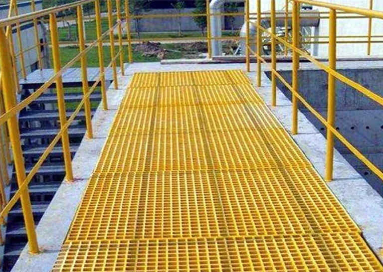
FRP grating installation for industrial floors should be coordinated from an approved support and panel layout, not from total floor area alone. Buyers should send the molded or pultruded construction, product series when known, panel depth and mesh or bar spacing, bearing direction, support lines and clear spans, required bearing, panel joints and clearances, cutouts, clips, edge treatment, transitions, loads, exposure, quantities and drawing revisions. QY Metal Tech can review the specified panel, fabrication, marking, accessory and packing scope; the responsible engineer and installer must approve the support design, fastening plan and field installation.
What buyers should send: A useful FRP grating installation drawing identifies every support line, clear span, panel mark, bearing direction, finished size, joint, removable area, cutout, edge condition, clip or fastener location, transition and site interface. Match the drawing to the exact molded or pultruded product and load requirement. Verify field dimensions before release, and keep structural, installation and local-compliance approval with the responsible project parties.
When this industrial-floor checklist is useful
Use it for platforms, mezzanine access, process floors, maintenance walkways and equipment areas where multiple FRP panels must align with steelwork, curbs, walls, openings, stairs or removable access zones. It is especially useful when the buyer has a support framing drawing but still needs a panel schedule, cut list and quotation package.
This is not a step-by-step field installation manual. It does not select support sections, set clip spacing, approve a load table or replace the project engineer's design. For product selection, start with molded FRP grating or pultruded FRP grating. For verified load-table inputs, use the FRP load table and support span guide.
Installation drawing fields to coordinate before RFQ
| Drawing or schedule field | What the buyer should show | Why it changes the quotation |
|---|---|---|
| Product construction | Molded or pultruded, exact series when known | Construction changes bearing-direction, cutting and support review |
| Panel geometry | Depth, mesh or bearing-bar spacing, width and length | Identifies the quotation basis and panel schedule |
| Bearing direction | Arrow or note on every directional panel mark | Prevents a pultruded or rectangular panel from being rotated |
| Support lines | Beam, angle, ledge or frame location with clear spans | Connects panel limits to the project support layout |
| Required bearing | Project-defined support contact at edges and intermediate lines | Prevents overall panel size from being mistaken for clear span |
| Panel joints | Joint locations, adjacent marks and removable zones | Affects panel breakdown, clips, marking and packing sequence |
| Perimeter and clearance | Wall, curb, column, equipment and transition relationship | Defines finished envelope and site interface without inventing a universal gap |
| Cutouts and notches | Size, centerline, radius, edge distance and support relationship | Affects fabrication, edge treatment and panel marking |
| Clips and fasteners | Project type, material, location and responsibility | Separates accessory supply from installation approval |
| Surface and exposure | Grit or other surface wording, resin request and environment | Keeps selection tied to the buyer's project document |
| Inspection and revision | Drawing number, revision, field-check status and hold point | Prevents outdated dimensions from controlling production |
Do not copy support, bearing, clearance or clip values from another manufacturer's product. Use the exact selected product record, project calculation and approved drawing. If any value is still open, label it as a buyer or engineer confirmation item rather than a QY recommendation.
Molded and pultruded layouts need different checks
| Coordination question | Molded FRP grating | Pultruded FRP grating |
|---|---|---|
| Direction | Square grids may appear similar in more than one direction; rectangular patterns still need orientation | Primary bearing bars and span direction must be clearly marked |
| Panel breakdown | Grid pattern, closed or partial cells and cut locations affect finished edges | Bearing-bar and cross-rod relationship affects cut pieces and panel marks |
| Support review | Show every perimeter and internal support under the selected panel layout | Show supports perpendicular to the primary bearing direction and all clear spans |
| Adjacent panels | Identify joints, removable panels and connecting accessory scope | Identify aligned bearing direction, joints and cross-rod relationship |
| Release evidence | Product series, layout, cut list and project approval | Product series, bearing direction, layout, cut list and project approval |
This comparison routes information; it does not declare either construction suitable. The selected series, load case, deflection criterion, exposure and support design control the decision.
Build the drawing package in four layers
1. Support layout
Show structural support centerlines and edges, clear openings, direction of span, curbs, frames, ledges, equipment bases, stairs and transitions. Identify which supports already exist and which are by others. A photograph can help explain access, but it cannot replace dimensions or engineering approval.
2. Panel layout and mark plan
Assign a unique mark to every panel type or finished piece. Show outside dimensions, orientation, joints, removable panels, cutouts and site interfaces. Keep the same marks in the drawing, quantity schedule and package labels.
3. Accessory and interface plan
Mark the specified clips, fasteners, connecting accessories, edge angles and removable-area hardware. The FRP clips and hold-down guide owns accessory selection inputs; this page coordinates their locations and responsibilities on an industrial-floor drawing.
4. Release and field-verification record
State who checks site dimensions, who approves the support and fastening design, which drawing revision controls fabrication and what hold point applies before release. Record changes at columns, pipes, drains and equipment instead of asking the installer to resolve them from a generic plan.
Cutouts, penetrations and unsupported edges
Mark every pipe, column, duct, drain and maintenance opening with dimensions from named datums. Show whether the feature is an internal cutout or an edge notch, and identify the surrounding support or frame detail. Use the FRP cutout, notch and edge-trim guide for fabrication fields.
QY can review submitted finished dimensions, panel marks and cutting notes. QY should not state that a cut panel remains structurally suitable unless the selected product, support condition, load requirement and responsible approval are documented.
For substation, transformer, generator or other buyer-defined electrical areas, use the FRP grating electrical-access RFQ checklist to add the required electrical, fire, drainage, containment, removable-panel and approval evidence without changing this page’s installation-drawing scope.
QY evidence and scope boundary
The featured image is an existing QY FRP walkway image showing grating panels in an industrial platform setting. It supports the product family and application context. It does not reveal the selected series, hidden supports, clear span, clip plan, load calculation, resin, field dimensions or installed compliance.
QY's useful scope is to compare the submitted panel schedule and drawings with the requested construction, finished sizes, orientation, cutouts, accessories, marks, quantity and packing. The existing QY drawing and project service process supports that quotation review. The mining walkway selection guide adds zone, exposure, traffic, load and layout inputs for mining applications. Final structural design, site measurement, installation procedure and acceptance remain with the responsible project parties.
Plain-language drawing terms
- Support line: The drawing location where the panel bears on a structural edge, beam, angle, ledge or frame.
- Clear span: The unobstructed distance between supporting edges under the panel, not the overall panel length.
- Panel mark: A unique identifier connecting a finished panel to the drawing, quantity schedule and package label.
- Bearing direction: The direction in which the primary load-carrying members span between supports; it must be explicit for directional products.
- Hold point: A required review or inspection stage that must be completed before the next project step proceeds.
RFQ checklist for an industrial FRP floor
Send the following through QY Metal Tech's contact page:
- Application, floor area and current plan/elevation revisions.
- Molded or pultruded construction and exact product series when specified.
- Panel depth, mesh or bar spacing, surface, resin wording and color.
- Project load case, deflection criterion and approved support basis.
- Support layout, clear spans, bearing direction and required bearing details.
- Panel mark plan, finished sizes, joints and removable access areas.
- Cutouts, notches, transitions, curbs, walls, equipment and edge interfaces.
- Clip, fastener, support-angle and accessory schedule with supply responsibility.
- Field-verification status, drawing approver and fabrication-release hold point.
- Quantity by mark, spare quantity, packing sequence, labels and destination.
Frequently asked questions
Can FRP grating be installed from total square meters alone?
No. A usable package also needs the exact product, support layout, clear spans, bearing direction, panel marks, finished sizes, joints, cutouts, accessories and approved drawings.
Should every FRP floor panel have a mark?
Panel marks are useful when finished sizes, orientations, cutouts or installation positions differ. Use the same mark on drawings, schedules and package labels.
Can QY determine clip spacing from an installation photo?
No. Clip type, material, quantity and location depend on the selected product, support, project loads, manufacturer data and approved fastening plan.
Who approves the FRP grating support and installation design?
The responsible engineer, asset owner or other project approval party should approve the support, load, fastening, field-installation and local requirements. QY can review the specified supply and quotation scope.
Related links
Related products and RFQ guides
- FRP grating productsOpen the related product family section.
- FRP grating topic entryFRP grating family page for molded FRP grating, trench covers, car wash grating, tree grates and wet or corrosive access areas.
- FRP trench coversRelated product or guide page.
- FRP grating selection guideRelated product or guide page.
- FRP Grating vs Galvanized Steel Grating for Wet AreasComparison guide for wet or corrosive area grating selection, covering FRP grating and galvanized steel grating by environment, traffic, support, cutouts and quotation details.
- FRP Grating RFQ Checklist for Corrosive and Wet FlooringFRP grating RFQ checklist covering wet or corrosive environment, panel size, support condition, thickness, mesh size, surface, color or resin request, quantity and destination.


