

Steel Grating
Steel Bar Grating
Steel bar grating is open-grid flooring whose bearing bars carry load between supports. Select bar size and spacing for the required load and clear span, then specify panel dimensions, finish, cutouts and fixings. Overall panel length and unsupported span are different dimensions.
RFQ quick details
Product overview
Steel Bar Grating selection for project RFQs
QY Metal Tech supports international project buyers with drawing-based RFQ review, custom fabrication discussion, surface finish selection and export packing notes from Wuxi, Jiangsu, China.
Steel Bar Grating specification path
| Bearing bar | Bar height, thickness, spacing and bearing direction are the first details to confirm. |
|---|---|
| Cross bar and opening | Cross bar pitch, smooth or serrated surface and open area affect drainage, grip and cost. |
| Panel size | Overall size, cutouts, banding, toe plate and fixing clips should follow drawings where possible. |
| Load condition | State the clear span, support arrangement, uniform load and any concentrated or wheel load with its contact area. Panel dimensions alone do not establish load capacity. |
| Finish | Hot-dip galvanized, untreated carbon steel, painted or stainless options depend on the environment. |
| Packing and marks | Bundle sequence, panel marks, pallet size and loading plan should be agreed when many panels are shipped together. |
Terminology and selection reference: ANSI/NAAMM MBG 531-24 (2024).
Standards reference
Standards and finish references can be reviewed by project requirement
- Steel grating can be reviewed according to drawings and standards such as YB/T 4001.1, ANSI/NAAMM MBG 531 or BS 4592 when required.
- Hot-dip galvanizing can be specified according to ISO 1461 or ASTM A123/A123M when a defined zinc coating reference is needed.
- Platform, stair and access projects may refer to ISO 14122 or local safety requirements for walking surfaces and guardrail interfaces.
- Final specification should follow project drawings, load notes, local codes and buyer approval documents.
Specification examples
Common Steel Bar Grating model expressions
| G325/30/100 | 32 x 5 mm bearing bar, 30 mm bearing bar pitch and 100 mm cross bar pitch. |
|---|---|
| G255/30/100 | 25 x 5 mm bearing bar for light to medium duty access areas. |
| G405/30/100 | 40 x 5 mm bearing bar reviewed for longer span or heavier load. |
| Serrated G325/30/100 | Serrated surface option for wet, oily or outdoor walking areas. |
Use these examples as RFQ shorthand, then confirm final dimensions, load, material, finish and drawings before production.
Applications
Steel Bar Grating applications and project references
These references help buyers connect steel bar grating specifications with real site conditions, fabrication details, packing requirements and installation expectations.
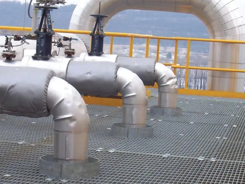
Industrial platforms
Walkways, mezzanines and equipment access floors for factories and plants.
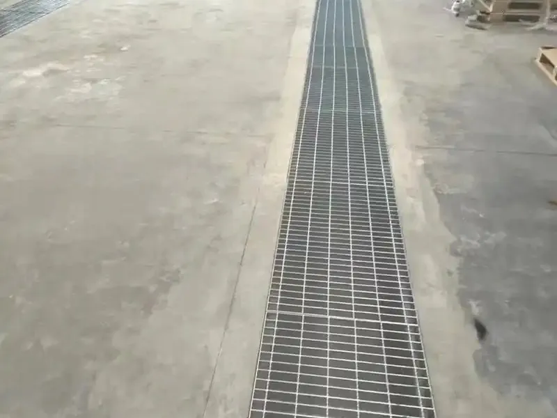
Drainage and trench covers
Open grating panels for drainage channels, service trenches and maintenance access.
Pre-shipment inspection
Dimension, welding and surface checks help confirm panels before export packing.
Steel grating technical references
Use the load tables with their stated standard editions and design assumptions. The separate 11-W-4 specification describes a different bearing-bar spacing from 19-W-4 and is not an interchangeable load rating. Confirm the required specification and project loads with the quotation.
Technical checks before quotation
- Confirm bearing-bar center distance, cross-bar type and panel dimensions.
- Select the load-table row from clear span, support condition, load direction and deflection limit.
- Confirm material and finish, including galvanized, painted or stainless requirements.
RFQ checklist
Send steel bar grating details for a faster quote
For faster quotation support, include dimensions, material, finish, application, quantity and destination for steel bar grating. Drawings, sketches, replacement photos or old specifications are welcome when the product must match an existing project.
Steel Bar Grating RFQ checklist
- Bearing bar size, spacing and bearing direction
- Panel size, support span, cutouts and banding details
- Load condition, finish, quantity and destination
- Drawings, sketches, old samples or project photos when available
FAQ
Steel Bar Grating buyer questions
What grating size do I need for my span?
For Q235 /30/100 grating under a 4 kN/m² uniform load with 4 mm deflection, recommended maximum spans are: G255 1260 mm, G325 1520 mm, G405 1790 mm, G505 2120 mm and G605 2430 mm. Vehicle, point or heavy loads need a separate check against the load table and your engineer’s criteria.
What does a code like G325/30/100 mean?
It means 32 × 5 mm bearing bars at 30 mm pitch, with cross bars at 100 mm pitch. US projects often specify 11-W-4 instead; that is a different pitch system and should not be confused with 19-W-4.
What panel widths can you supply?
Width is measured across the bearing bars: (bar count − 1) × pitch + bar thickness. With 30 mm pitch and 5 mm bars, nominal widths run from 185 mm to 995 mm. Panel length follows your span and drawing.
Galvanized, painted or stainless: which finish should I choose?
Hot-dip galvanizing to ISO 1461 or ASTM A123 is the usual choice for outdoor carbon steel grating. Painted grating suits dry indoor areas. Stainless steel is reviewed for corrosive or hygiene-sensitive areas.
Should I choose serrated or smooth grating?
Serrated bars are used where floors can get wet, oily or icy. The serrations reduce the effective bar depth, so the load capacity must be confirmed and a deeper bar may be needed.
How is grating fixed to the supporting steel?
With fixing clips, or by welding where the project allows it. Banding (flush, load-carrying or trim), toe plates, notches and cutouts follow your drawing.
Is there a minimum order, and can I get a sample?
The MOQ is 50 panels; we quote from your drawings and quantities. Samples are available, with the sample and freight costs paid by the buyer.
Related paths
Continue from this product
Need a practical steel bar grating quotation?
Send drawings, specifications, quantity, destination and packing notes. We will review the details before replying with quotation support.
Reading the downloadable reference
Steel grating load-table scope and nominal panel widths
The downloadable Chinese reference is labeled YB/T 4001.1-2007, tables E1-E7, printed pages 26-32. The load symbols and nominal-width data are explained below as product-page text. This historical extract is a different source from the calculated screening tables linked on this website; their editions and assumptions must not be mixed.
Read the load case and deflection together
| Source symbol or note | Meaning in the downloaded extract |
|---|---|
| U – kN/m² | Safe imposed uniformly distributed load, as defined in the source. It is not a wheel load or a panel total in kilograms. |
| C – kN/m | Safe imposed line load at the span center, acting perpendicular to the bearing bars. It is not an isolated point load. |
| D – mm | Maximum deflection under the corresponding listed imposed load. Read D with its U or C row and the same span column. |
| Source display boundary | The source notes that its populated data region has less than 4 mm maximum deflection under a 2 kN/m² uniform load. This is not the separate website screening table’s load/deflection basis. An empty source cell is not a zero load or an approved span. |
| Theoretical weight | The source describes hot-dip galvanized grating with a 1 m length; its table weight heading is kg/m². Do not treat a weight value as an imposed-load rating or omit the actual panel dimensions. |
Match the table to the actual bearing-bar family
| Source table | Product geometry covered |
|---|---|
| E1 | Welded flat-bar grating, 30 mm bearing-bar center spacing. |
| E2 | Welded flat-bar grating, 40 mm bearing-bar center spacing. |
| E3 | Welded flat-bar grating, 20 mm bearing-bar center spacing. |
| E4 | Welded I-section bearing-bar grating, 30 mm center spacing. |
| E5 | Welded I-section bearing-bar grating, 40 mm center spacing. |
| E6 | Heavy-duty welded grating; match the listed bearing bar, cross bar and model rather than a generic heavy-duty name. |
Confirm the exact model, material, bearing direction, clear span, support/bearing detail, load type, load area and deflection criterion in the project drawing. Do not transfer a flat-bar result to I-section grating, steel to FRP, or a metric pitch to a different imperial pattern. The original load matrices remain in the download; no additional capacity values are inferred here.
Nominal width by bearing-bar count – source table E7
All 93 bar-count records from E7 are set out below. The dimensional cross-check is nominal width = (bar count – 1) × bearing-bar pitch + bearing-bar thickness. Width is across the bearing bars, not the support span. Banding, installation clearance, edge details and manufacturing tolerances still follow the agreed drawing.
Dimensions are in mm. One inconsistent source field is marked “Confirm drawing” rather than silently corrected or presented as a verified dimension.
Source table E7: 20 mm bearing-bar pitch
| Bearing-bar count | 3 mm bars: width (mm) | 5 mm bars: width (mm) |
|---|---|---|
| 51 | 1003 | 1005 |
| 50 | 983 | 985 |
| 49 | 963 | 965 |
| 48 | 943 | 945 |
| 47 | 923 | 925 |
| 46 | 903 | 905 |
| 45 | 883 | 885 |
| 44 | 863 | 865 |
| 43 | 843 | 845 |
| 42 | 823 | 825 |
| 41 | 803 | 805 |
| 40 | 783 | 785 |
| 39 | 763 | 765 |
| 38 | 743 | 745 |
| 37 | 723 | 725 |
| 36 | 703 | 705 |
| 35 | 683 | 685 |
| 34 | 663 | 665 |
| 33 | 643 | 645 |
| 32 | 623 | 625 |
| 31 | 603 | 605 |
| 30 | 583 | 585 |
| 29 | 563 | 565 |
| 28 | 543 | 545 |
| 27 | 523 | 525 |
| 26 | 503 | 505 |
| 25 | 483 | 485 |
| 24 | 463 | 465 |
| 23 | 443 | 445 |
| 22 | 423 | 425 |
| 21 | 403 | 405 |
| 20 | 383 | 385 |
| 19 | 363 | 365 |
| 18 | 343 | 345 |
| 17 | 323 | 325 |
| 16 | 303 | 305 |
| 15 | 283 | 285 |
| 14 | 263 | 265 |
| 13 | 243 | 245 |
| 12 | 223 | 225 |
| 11 | 203 | 205 |
| 10 | 183 | 185 |
Source table E7: 30 mm bearing-bar pitch
| Bearing-bar count | 3 mm bars: width (mm) | 5 mm bars: width (mm) |
|---|---|---|
| 34 | 993 | 995 |
| 33 | 963 | 965 |
| 32 | 933 | 935 |
| 31 | 903 | 905 |
| 30 | 873 | 875 |
| 29 | 843 | Confirm drawing† |
| 28 | 813 | 815 |
| 27 | 783 | 785 |
| 26 | 753 | 755 |
| 25 | 723 | 725 |
| 24 | 693 | 695 |
| 23 | 663 | 665 |
| 22 | 633 | 635 |
| 21 | 603 | 605 |
| 20 | 573 | 575 |
| 19 | 543 | 545 |
| 18 | 513 | 515 |
| 17 | 483 | 485 |
| 16 | 453 | 455 |
| 15 | 423 | 425 |
| 14 | 393 | 395 |
| 13 | 363 | 365 |
| 12 | 333 | 335 |
| 11 | 303 | 305 |
| 10 | 273 | 275 |
| 9 | 243 | 245 |
| 8 | 213 | 215 |
| 7 | 183 | 185 |
Source table E7: 40 mm bearing-bar pitch
| Bearing-bar count | 3 mm bars: width (mm) | 5 mm bars: width (mm) |
|---|---|---|
| 26 | 1003 | 1005 |
| 25 | 963 | 965 |
| 24 | 923 | 925 |
| 23 | 883 | 885 |
| 22 | 843 | 845 |
| 21 | 803 | 805 |
| 20 | 763 | 765 |
| 19 | 723 | 725 |
| 18 | 683 | 685 |
| 17 | 643 | 645 |
| 16 | 603 | 605 |
| 15 | 563 | 565 |
| 14 | 523 | 525 |
| 13 | 483 | 485 |
| 12 | 443 | 445 |
| 11 | 403 | 405 |
| 10 | 363 | 365 |
| 9 | 323 | 325 |
| 8 | 283 | 285 |
| 7 | 243 | 245 |
| 6 | 203 | 205 |
| 5 | 163 | 165 |
| 4 | 123 | 125 |
11-W-4 project specification and inspection
Source: QY-SG-3PS-11W4-01, Rev. 1.0 / 24 Jul 2026, Section 05 53 00. This editable project reference covers light-duty carbon steel welded grating, bearing bars, cross bars, banding, anchors, clips and accessories. The original PDF download remains available.
Separate product basis: 11-W-4 has 11/16 in nominal bearing-bar centers. It is not 19-W-4, and this specification is not the historical YB/T load matrix or a capacity rating. Blank project fields below require an approved entry; the designation alone does not determine bearing-bar depth or load capacity.
Design inputs and reference editions
- State uniform load in psf or kPa and concentrated load in lb or kN, including its location.
- Record clear span and support width in inches or mm. State the service-deflection limit as the lesser of the specified L/divisor or absolute in/mm limit, unless project criteria differ.
- Select bar depth using evidence for the exact product, span, supports and loads. Do not combine unit systems or reference editions without review.
- Specify the slip-test method, surface condition and acceptance value. A slip claim needs an accepted report for that exact tested surface.
The PDF lists ANSI/NAAMM MBG 531-24; ASTM A1011/A1011M-25 for applicable bearing-bar input; ASTM A510/A510M-25 for applicable cross-bar input; ASTM A123/A123M-24 for specified after-fabrication galvanizing; and ASTM A153/A153M-23 for applicable hardware. These are the source document’s editions, not a claim that every listed standard applies to every item. The contract or authority-adopted edition and project structural, accessibility, slip, fire/life-safety and owner requirements govern.
Where an accessible route is required, review 2010 ADA Sections 302.1 and 302.3 and applicable exceptions: openings must not pass a sphere greater than 1/2 in (13 mm), and elongated openings have their long dimension perpendicular to dominant travel. This is a project check, not blanket ADA certification of a grating designation.
Product selections to put on the approved drawing
| Parameter | Specified requirement |
|---|---|
| Designation | 11-W-4 welded steel bar grating, subject to project confirmation |
| Bearing-bar spacing | 11/16 in nominal on center; state metric manufacturing control and tolerance |
| Bearing-bar thickness | 3/16 in nominal or project-approved equivalent |
| Bearing-bar depth | [project entry] in / [project entry] mm, selected from approved load/deflection evidence |
| Cross-bar spacing | 4 in nominal on center |
| Surface | Plain / serrated / project-verified slip-resistant option |
| Panel size | [project entry] x [project entry] with bearing-bar direction shown on shop drawings |
| Banding | Flush / load-carrying / trim banding as detailed |
| Finish | Bare / after-fabrication hot-dip galvanized / project coating system |
Submittals, material control and fabrication
- Submit exact designation, bar dimensions and spacing, cross bars, material, surface and finish; matching load tables/calculations; and drawings showing direction, supports, penetrations, cutouts, banding, joints, anchors and removable sections.
- Supply material, coating, fastener and dimensional records. Required slip or other tests must identify the exact product and test condition.
- Use approved carbon-steel grades and compatible banding, clips and fasteners. Keep heat/lot and component traceability, use qualified fabrication, and resolve drawing/specification conflicts before fabrication.
- Fabricate to the approved layout, bearing direction and tolerances. Detail cutouts, banding and permitted repairs; mark removable panels. Remove sharp projections without reducing required sections.
- Keep fabricated-product galvanizing and hardware requirements distinct. Use the applicable approved process and repair method, with coating-batch identity maintained.
- Specify attachment type, quantity and locations on the drawing; the source leaves the quantity open. Use captive or tamper-resistant details where required, not an assumed universal clip count.
Any substitution must match the technical, dimensional, load, finish and evidence package. Document material grades, and select clips/fasteners for the substrate, exposure and maintenance duty. Supply specified washers and support seats. Bearing bars span between supports; apply adopted ANSI/NAAMM and any tighter project tolerances, and match-mark adjacent panels where required. Compliance with load, slip, accessibility or coating requirements is not established by the product name alone.
Delivery and installation controls
Bundle and mark by area or panel ID. Store dry, ventilated and above ground; avoid wet, unventilated stacking, protect finished surfaces and edges and avoid distorting bundles. Verify support elevations, alignment and bearing before placing panels. Obtain approval before site cutting or alterations. Provide full, even bearing without loose shims, maintain approved openings and trip-edge control, and secure panels without crushing them. Record coating repairs and keep removable sections identifiable and restrained in service.
Installed-panel acceptance records
| Inspection | Acceptance record |
|---|---|
| Panel identity / drawing | Correct panel ID, revision and location |
| Bearing direction / support | Correct span direction, bearing width and support contact |
| Openings / joints | Approved size, orientation and trip-edge control |
| Fasteners | Correct type, quantity, location and security |
| Finish | Damage repaired and no unacceptable sharp edges |
| Removable access | Operates, is restrained in service and is identified |
Clean and protect the installation and prevent construction overloading. Replace damage that cannot be restored by an approved method. Handover includes as-built drawings, material/coating records, accepted deviations, repairs and maintenance information, with the final evidence revision identified.
Quick span guide
Recommended maximum span by model (Q235, /30/100)
Span at which a 4 kN/m² uniform load gives 4 mm deflection, calculated with the YB/T 4001.1—2019 Annex C method.
| Model | Bearing bar | Recommended max. span |
|---|---|---|
| G255/30/100 | 25 × 5 mm | 1260 mm |
| G325/30/100 | 32 × 5 mm | 1520 mm |
| G405/30/100 | 40 × 5 mm | 1790 mm |
| G505/30/100 | 50 × 5 mm | 2120 mm |
| G605/30/100 | 60 × 5 mm | 2430 mm |
Selection path
Specification, data and project references
1 · Check technical data
2 · See project references
3 · Datasheet and quotation
Order terms
- MOQ: 50 pcs (panels, rolls or pieces)
- Samples available; sample and freight costs paid by the buyer
- Payment: 30% deposit, 70% before shipment
- Lead time: usually 30 days ex-works after deposit and drawing approval
- Quotation in 24–48 hours on working days
- Drawings: PDF, DWG, DXF, JPG, PNG, WebP up to 12 MB
Product datasheet
Steel Bar Grating datasheet
2-page PDF: typical specifications, what we confirm before quotation, RFQ checklist and contact details. (451 KB)
RFQ form
Request Steel Bar Grating quotation
Upload drawings if available. Include product size, material, finish, quantity, destination and application notes for a faster technical response.
Related links
Related product and RFQ resources
- Steel grating product catalogBrowse the related product family section.
- 19-W-4 steel gratingCompare material, bar spacing and project specification details.
- Carbon steel bar gratingCompare material, bar spacing and project specification details.
- Steel Grating RFQ Checklist for International BuyersRFQ checklist for steel grating buyers covering application, panel or opening size, bearing bar direction, support span, finish, quantity, packing, destination and drawings.
- FRP Grating vs Galvanized Steel Grating for Wet AreasComparison guide for wet or corrosive area grating selection, covering FRP grating and galvanized steel grating by environment, traffic, support, cutouts and quotation details.
- How to Choose Steel Grating for Industrial PlatformsIndustrial platform grating selection guide covering platform use, support span, bearing direction, panel layout, finish, cutouts, fixing clips, drawings and RFQ details.
- Send project RFQ detailsSend drawings, dimensions, finish notes, quantity and destination for review.
Factory verification and order terms
Video factory visits by appointment
Video factory visits can be arranged in advance. Contact our sales team to agree a time, platform and accessible production, inspection or packing areas. Other customers’ information and confidential areas are not shown.
Lead time: usually 30 days ex-works
For regular orders, production usually takes 30 days ex-works, counted from receipt of the deposit and approval of the drawings. Larger or special orders, and stock availability, are confirmed in the written quotation. Production and transport times are stated separately in the quotation or contract.
Written quotation and delivery terms
Trade terms are agreed for each order and logistics arrangement. The written quotation specifies the applicable Incoterms® 2020 rule, named delivery place or port of shipment, and whether freight, insurance and taxes are included. For containers handed to a carrier before vessel loading, FCA is considered rather than automatically using FOB.
Quality concerns and corrective action
Please provide the order number, affected quantity, photos or video, and relevant measurements or inspection records when reporting a quality concern. If responsibility is confirmed to lie with us, a remedy such as repair, additional supply, replacement, refund or price adjustment is agreed under the contract. Costs and the action plan are confirmed in writing; no unconditional return or fixed resolution period is promised.


