
Replacement W-Beam Guardrail Parts: How to Match Rails, Posts and Hardware
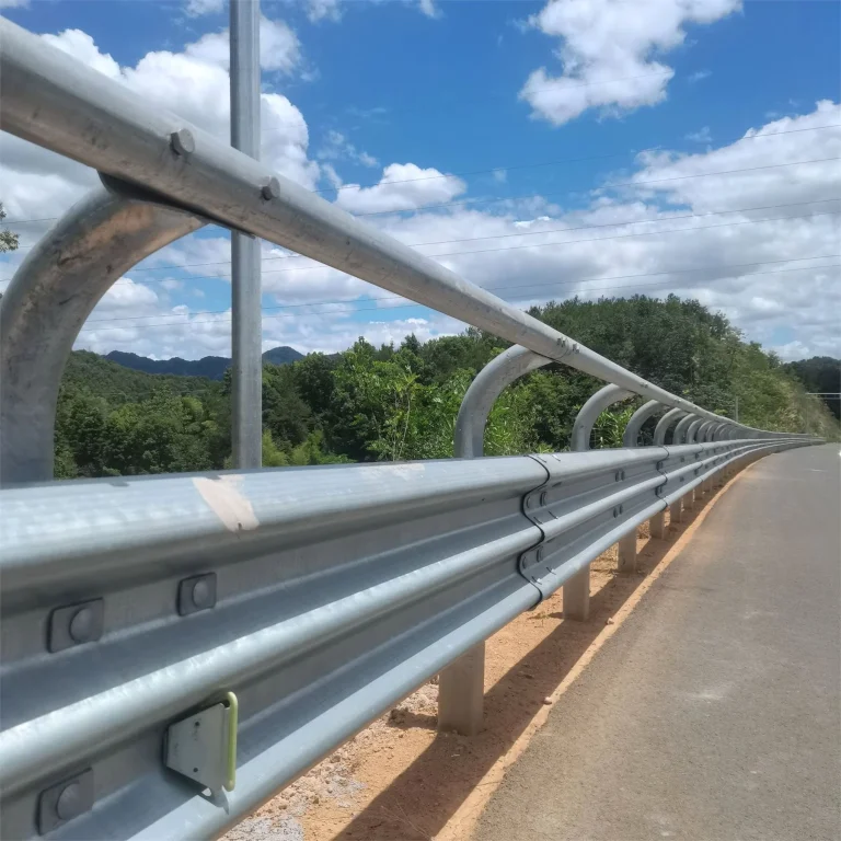
Replacement W-beam guardrail parts should be matched from the existing system records, rail profile, visible markings, panel length, hole pattern, post and spacer arrangement, fasteners, terminals, transitions, coating and site layout. A generic photo or one dimension is not enough to approve an interchangeable part. QY can review a documented supply RFQ, while the project owner, engineer or relevant authority remains responsible for replacement approval and installation requirements.
What buyers should send: To request replacement W-beam guardrail parts, send the original drawing or order reference if available, clear photos of the complete damaged area and all visible markings, rail profile, panel length, hole and slot pattern, post and spacer details, bolt and nut details, terminal or transition connection, coating, quantity and destination. Mark which parts are being replaced and which existing parts must remain. Do not rely on visual similarity alone for a safety-critical roadside system.
Start with the existing guardrail system
A replacement request is different from a new guardrail RFQ. The new component must connect to parts already on site, so the buyer should first identify the complete assembly around the damaged area. The rail alone may not define the post, blockout or spacer, fastener set, terminal, transition or connection detail.
Use the original approved drawing, bill of materials, maintenance record or previous order reference whenever it is available. If records are incomplete, prepare a marked photo set and dimensioned sketch before quotation.
For product context, see highway guardrails, guardrail posts, spacers and bolts and guardrail terminals and transitions.
Identification details buyers should collect
| Identification field | Why it matters | Useful RFQ evidence |
|---|---|---|
| Existing system reference | Connects the request to the correct project basis | Approved drawing, previous purchase order or maintenance record |
| Rail profile | Separates W-beam, Thrie-beam and other profiles | End-view photo and profile dimensions |
| Markings or stamps | May support manufacturer, batch or specification review | Close photo plus a wider photo showing where the marking appears |
| Panel length and hole pattern | Affects alignment with existing rails and posts | Overall length, end-hole layout, splice slots and post-hole positions |
| Material thickness or gauge | Must come from records or reliable measurement | Drawing value, previous specification or measured thickness with method noted |
| Post and spacer arrangement | Defines the rail support connection | Post profile, length, hole locations, spacer or blockout shape and orientation |
| Fastener set | Bolts, nuts and washers must match the connection detail | Head style, diameter, length, thread, quantity and photos |
| Terminal or transition | End and transition pieces are not generic rail panels | Part drawing, connection photo and adjoining component details |
| Finish and condition | Defines the requested supply finish and replacement scope | Coating request, corrosion photos and damaged-area limits |
| Site layout | Shows curves, traffic face, lap direction and nearby structures | Plan sketch, direction arrows and station or location references |
Do not decode a stamp from memory or assume that every marking system means the same thing. Record the marking exactly as it appears and send it with the project documents.
Decide the replacement supply boundary
| Site condition | Parts to identify | Questions before quotation |
|---|---|---|
| Damaged rail panel only | Rail profile, length, holes and splice area | Are adjoining panels, posts and hardware reusable and approved to remain? |
| Bent post or spacer | Post, base or embedment, spacer and connection hardware | Is the foundation or soil condition also damaged? |
| Missing or damaged hardware | Bolt, nut, washer and connection location | Is there an original hardware schedule or drawing? |
| Terminal damage | Terminal components, rail connection, posts and hardware | Which complete terminal system and revision is installed? |
| Transition damage | Both adjoining systems and the transition assembly | Which parts remain, and where does the replacement boundary begin and end? |
| Curved roadside section | Rail curvature, panel length, holes, posts and orientation | Is the required curve defined by an approved layout or field survey? |
If the remaining assembly cannot be positively identified, the buyer should escalate the decision to the project owner or responsible engineer instead of ordering a visually similar component.
Photos and drawings to send
Use one photo set for context and another for measurement:
- A wide photo showing the damaged area, traffic face and adjoining rail sections.
- Front, back, end and connection views of the affected component.
- Close photos of every readable stamp, label or marking.
- A scale or ruler beside hole spacing, slot size, profile depth and component width.
- Photos of the post, spacer or blockout, bolts, nuts and washers.
- Terminal, transition, curve and nearby obstruction details where relevant.
- A marked sketch showing retained parts, replacement parts, quantity and orientation.
Photos support identification, but dimensions and project records should control the RFQ. Perspective can distort length, hole spacing and profile shape.
Terms to clarify
- W-beam rail: A corrugated roadside rail profile. The name alone does not define length, thickness, holes, coating or system approval.
- Post: The vertical support component. Its profile, length, holes, base or embedment and spacing must be identified.
- Spacer or blockout: A component between the rail and post. Buyers should show its shape, orientation and connection hardware.
- Splice bolt: A fastener used at rail-panel overlaps. Confirm the complete fastener requirement from the system drawing.
- Terminal or transition: A designed end or connection assembly. It should be identified as a system, not replaced from appearance alone.
RFQ checklist
Before requesting quotation, confirm:
- Original drawing, order, specification or maintenance reference.
- Guardrail system and rail profile.
- Exact visible markings or stamps.
- Panel length, profile dimensions, hole and slot pattern.
- Material thickness or gauge from a reliable source.
- Post, spacer or blockout and foundation details.
- Bolt, nut, washer and connection requirements.
- Terminal, transition, curve and lap-direction details.
- Coating, quantity, packing, destination and delivery terms if available.
- Marked photos showing replacement and retained components.
- Project owner or engineer review requirements.
Related QY pages
- Highway guardrails for the main product context.
- Highway guardrail RFQ checklist for a complete new-system inquiry.
- Guardrail posts, spacers and bolts for support and hardware details.
- W-beam splice bolts and lap direction for overlap information.
- Guardrail terminals and transitions for system-end details.
- Contact QY Metal Tech when the marked drawings, photos and quantities are ready.
FAQ
Can a replacement W-beam guardrail part be matched from one photo?
No. One photo may support an initial review, but it cannot reliably confirm profile, length, thickness, hole pattern, post connection, hardware, terminal system or project approval basis. Send records, dimensions and several marked views.
Which guardrail markings should buyers photograph?
Photograph every readable stamp, code or label exactly as it appears. Include a close view and a wider view showing its location on the rail, post, spacer, terminal or transition. Do not interpret the code unless the original documentation supports that interpretation.
Can a visually similar guardrail bolt be used as a replacement?
Visual similarity is not enough. Confirm the bolt type, diameter, length, head, thread, nut or washer set and connection location from the applicable drawing or approved system record.
Who should approve a roadside guardrail replacement?
The project owner, responsible engineer or relevant authority should determine the approved replacement and installation requirements. QY can review documented component details for quotation but does not replace project-specific approval.
Related links
Related products and RFQ guides
- Fencing and guardrails productsOpen the related product family section.
- Fencing and guardrails topic entryFencing and guardrail product pages for highway guardrails, welded mesh fence, chain link fence, double wire fence, municipal guardrails and railings.
- Welded mesh fenceRelated product or guide page.
- Chain link fenceRelated product or guide page.
- Welded Mesh Fence RFQ Guide for Site Boundary ProjectsRFQ guide for welded mesh fence projects covering boundary use, panel size, wire diameter, mesh opening, posts, finish, gates, accessories, quantity and destination.
- Chain Link Fence vs Welded Mesh Fence for Site Boundary RFQsFence comparison and RFQ guide covering chain link fence, welded mesh fence, panel or roll form, posts, coating, gates, accessories, quantity and destination.


