

Fencing & Guardrails
Municipal Guardrails
Municipal guardrails are modular road safety panels used on city roads, medians, sidewalks, crossings and public areas where vehicles and pedestrians need clear separation.
Files PDF, DWG, DXF, sketches and product photos are welcome.
Buyer overview
Municipal Guardrails Are Quoted by Panel Style, Post Layout and Finish
RFQs should confirm panel height and length, rail tube, vertical infill, post spacing, base plate or embedded fixing, coating color, reflectors, layout quantity and packing marks.
QY Metal Tech reviews layout drawings, site photos, road sections, color requirements, quantity and export packing notes so the guardrail panels match the installation sequence.
Panel style
Straight, curved, decorative or median guardrail style should match the road layout.
Panel size
Panel height, length, bottom clearance and module spacing should be confirmed by drawing.
Rail and frame
Top rail tube, frame size, vertical bars and infill pattern are reviewed before production.
Posts and fixing
Post section, spacing, base plate, anchors or embedded installation should be confirmed.
Finish & accessories
Galvanized base, powder coating color, reflectors, caps, bolts and connection parts should be listed.
Specification options
Municipal Guardrails Specification Options
Use these options to confirm panel style, post fixing, reflector accessories and coating details before quotation.
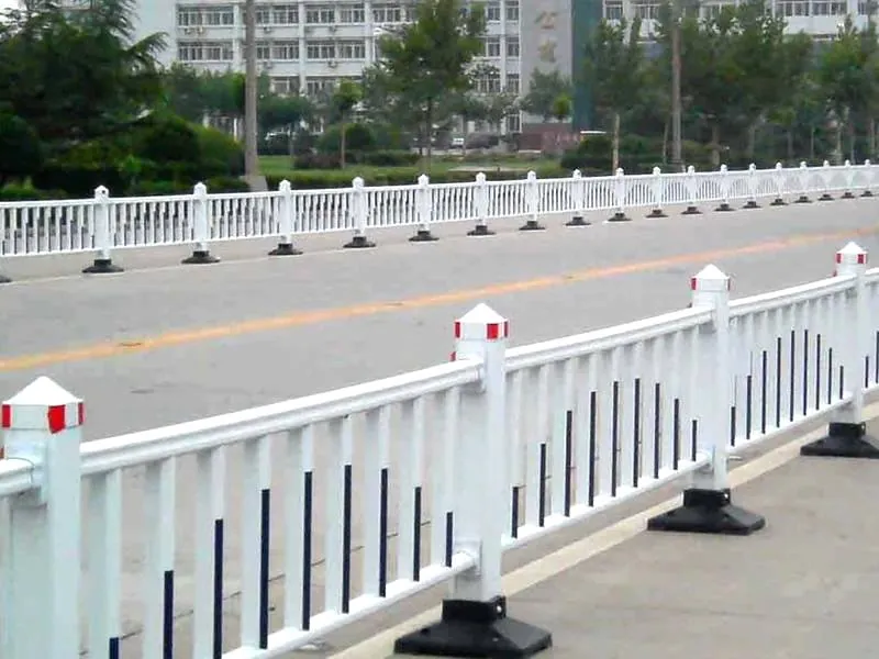
Panel style and height
Confirm guardrail style, height, section length and road alignment from the layout drawing.
Post spacing and fixing
Confirm post section, spacing, base plate or embedded fixing method before production.
Color and reflectors
Confirm powder coating color, reflector position, caps, bolts and connection accessories.
Municipal Guardrails Technical Reference
| Panel style | Straight, curved, decorative or median panelsMatch the city road, median or sidewalk layout before quotation. |
|---|---|
| Panel size | Panel height, section length and bottom clearanceConfirm from the project drawing or marked road photo. |
| Rail and infill | Top rail, frame tube and vertical infillList decorative infill and welded joint details before production. |
| Posts and fixing | Post section, spacing and fixing methodConfirm base plate, anchor bolts or embedded installation by location. |
| Color and reflectors | Powder coating color, galvanized base and reflectorsMatch caps, reflective plates and local project requirements. |
| Packing marks | Panel numbers, post groups and accessory cartonsPack and label by road section to support on-site installation. |
Design notes
Send the Road Layout, Post Fixing and Color Requirements
Guardrail panel height, section length, road alignment, post spacing and base fixing method decide whether the quotation can be prepared accurately.
For replacement or municipal maintenance projects, site photos, old panel dimensions and color references help confirm compatible panels when CAD drawings are not available.
Standards reference
Municipal Guardrail Standards and Finish References
- Municipal guardrail systems should be reviewed by road layout drawings, pedestrian safety requirements, panel height and local project rules.
- Post spacing, base plate size, anchor bolts, embedded posts and road alignment should be checked before production.
- Hot-dip galvanizing, powder coating or painting can be specified by outdoor exposure, project color and maintenance expectation.
- Final specification should follow approved drawings, color samples, reflector layout, accessory list and packing marks.
Specification examples
Common Municipal Guardrail RFQ Expressions
| 1200 mm pedestrian barrier | Common city guardrail height referenceFinal height, length and panel style follow the road layout drawing. |
|---|---|
| Road median panel set | Panel length, rail tube and vertical infillReview post spacing for continuous road separation. |
| Base-plate post system | Post section, base plate and anchor boltsConfirm reflector position for surface-mounted installation. |
| Powder-coated city color | Project color, coating system and reflectorsConfirm connection accessories before production. |
Use these expressions as RFQ shorthand, then confirm final panel height, length, rail size, post fixing, color, accessories and drawings before production.
Applications
Where Municipal Guardrails Are Commonly Used

Road medians and sidewalks
Modular panels for city roads, sidewalks, medians and pedestrian separation.

Crossings and public areas
Guardrails for crossings, schools, parks, stations and municipal facilities.
Replacement and color projects
Panels can be matched by old photos, color references, post spacing and section marks.
RFQ checklist
Send Municipal Guardrail Layout and Post Details
Include panel height, length, style, rail and post sizes, base plate or embedded fixing, coating color, reflectors, layout quantity and destination. Drawings or marked road photos help us quote faster.
Municipal Guardrails RFQ checklist
- Panel height, length, style and road layout
- Rail tube, frame, vertical bar and post spacing details
- Base plate, anchor bolts or embedded fixing method
- Coating color, reflectors, caps and connection accessories
- Layout quantity, destination, packing marks and drawings or photos
Project notes
Confirm Layout, Finish and Packing Before Production
For project supply, municipal guardrails should be checked against road layout, pedestrian route, post installation method, color requirement and export packing sequence before production.
Clear panel marks, post groups, accessory lists, reflectors and color references reduce revision time and help installers sort materials by road section.
Production and packing review
- Approved road layout, panel marks and post group sequence
- Rail tube, frame, infill pattern and welded joint review
- Coating color, reflectors, caps and accessory carton quantities
- Panel bundles packed and labeled by road section or crossing area
- Photos, packing list and loading details prepared before shipment
FAQ
Common Municipal Guardrails Questions
Where are municipal guardrails used?
City road medians, sidewalks, crossings, schools, parks, stations and other public areas where pedestrians and vehicles need clear separation.
What height is common for municipal guardrails?
1200 mm is a common pedestrian barrier height reference; final height, section length and style follow your road layout drawing.
How are the posts fixed?
With base plates and anchor bolts for surface mounting, or embedded in the ground or concrete. The method can differ by location along the route.
Can the color and reflectors be customized?
Yes. Powder coating color, reflectors, caps and connection parts follow your project color and layout.
Can you make curved or decorative sections?
Yes. Curved sections, decorative infill and special panel styles can be made from drawings or marked photos.
Can you match replacement panels for existing guardrails?
Yes. Send site photos, old panel dimensions, post spacing and a color reference so new panels fit the existing line.
Related paths
Continue from this product
Need a Practical Municipal Guardrails Quotation?
Include panel height, length, style, rail tube, post spacing, base fixing, coating color, reflectors, quantity, destination and any layout drawings or photos. We will review the details before quotation.
Industrial pedestrian barrier project references
Sources: QY-IGR-DS-01 and QY-IGR-INS-01, both Rev. 1.0 / 24 Jul 2026. These RFQ and installation references are available in the existing downloads.
Read the application boundary: these documents concern non-highway industrial pedestrian separation. They are an additional project-reference option within the guardrail range, not a universal specification for every municipal railing. They do not establish highway crashworthiness, fall-protection, handrail or vehicle-impact ratings. Required capacity must be supported by exact configuration evidence and project review.
Configuration and intended function
The source diagram illustrates a three-rail arrangement without assigning dimensions or an impact rating. Its intended uses are defining pedestrian routes and equipment exclusion zones, creating a visible maintainable process-area boundary, and accommodating straight runs, corners, returns, gates or removable sections. Choose the actual rail count, profiles, fixing method, corners, access and visibility for the approved project. Engineered impact duty needs project loads and supporting evidence.
Configuration options
| Feature | Options to define |
|---|---|
| Posts | Steel tube / fabricated steel / FRP profile; base-plated or embedded |
| Rails | 1, 2 or 3 rails; tube/profile size; horizontal spacing |
| Finish | Hot-dip galvanized, powder-coated, duplex or project-specified |
| Corners | Inline, 90°, variable angle or custom return |
| Access | Swing gate, removable rail, lift-out section or no access |
| Visibility | Color, reflective marking and floor interface |
Project duty and site inputs
| Input | Project entry |
|---|---|
| Protected people / asset | [project entry] |
| Vehicle / equipment type | [project entry] |
| Mass, speed and approach angle | [project entry] |
| Required design load or test level | [project entry] |
| Barrier height / rail count | [project entry] |
| Post spacing / run geometry | [project entry] |
| Substrate type and thickness | [project entry] |
| Concrete strength / reinforcement scan | [project entry] |
| Environment / chemicals / UV | [project entry] |
| Required finish / color | [project entry] |
| Governing code / owner standard | [project entry] |
The anchor interface needs design actions, concrete cracked/uncracked condition, edge distance, spacing, embedment, base-plate stiffness and an approved anchor product. Torque alone does not prove anchor capacity. State impact energy, deflection or load capacity only with traceable tests or calculations for the exact configuration, load case and boundary conditions accepted by the responsible designer.
Required submittals
| Submittal | Minimum content |
|---|---|
| General arrangement | Run lengths, corners, gates, clearances and interfaces |
| Fabrication drawing | Profiles, welds, holes, plates, tolerances and part IDs |
| Anchor schedule | Anchor type, approval, diameter, embedment, hole cleaning and torque |
| Material / finish | Grades, certificates, coating system and inspection |
| Design / test evidence | Exact configuration, load case, boundary conditions and acceptance |
| Installation plan | Survey, scanning, exclusion zone, sequence and inspection |
| Handover | As-built drawing, inspection record, maintenance plan and damaged-part rules |
RFQ release checks
- State the function and excluded uses; complete layout, loads, substrate and environmental data.
- Define exact material, finish, welding and fasteners, with engineered anchor selection.
- Label evidence as tested, calculated, supplier-supported or not yet verified.
- Agree inspection, maintenance and damaged-part replacement rules.
Record the approval chain
| Approval field | Name / date / reference |
|---|---|
| Prepared by | [project entry] |
| Technical review | [project entry] |
| Customer/designer approval | [project entry] |
| Approved drawing | [project entry] |
| Evidence attached | [project entry] |
Installation sequence and stop conditions
Permit and survey → set out → drill and clean → anchor and align → inspect and hand over. Stop for unknown substrate or embedded services, damaged concrete, missing anchor instructions, or a component/drawing mismatch. The guide supplies no universal drill diameter, embedment, torque, impact energy or capacity.
Responsibilities before work starts
| Role | Minimum responsibility |
|---|---|
| Customer/site | Permit, shutdown, access, floor records, service information and exclusion zone |
| Designer | Loads, layout, substrate acceptance, anchor design and approved drawing |
| Installer | Competent supervision, calibrated tools, drilling controls and inspection records |
| QY / supplier | Correct labeled components, approved submittals and replacement-part identification |
Safety and concrete-drilling controls
- Complete the task risk assessment, permit and required lockout/isolation.
- Locate embedded electricity, water, gas, post-tensioning and reinforcement before drilling, with competent interpretation of the scan.
- Control respirable crystalline silica under the applicable law and exposure-control plan, using the task-appropriate dust extraction/wet methods, housekeeping and respiratory program.
- Select eye, hearing, hand, foot and respiratory protection from the assessment and SDS. Barricade the work zone and control sparks, trip hazards, dust and overhead work.
- Avoid dry sweeping or compressed-air cleaning that disperses hazardous dust unless permitted by the applicable regulatory control method. Anchor-hole cleaning must still follow the approved anchor manufacturer’s instructions with appropriate dust controls.
For U.S. concrete work, consult OSHA 29 CFR 1926.1153. This reference does not replace the employer’s site-specific control plan or the anchor manufacturer’s approved installation instructions.
Tool and document readiness
| Item | Check |
|---|---|
| Approved drawing and anchor data | Current revision at workface |
| Scanner / locator | Suitable for substrate and interpreted by competent person |
| Drill and bit | Correct type/diameter; dust-control attachment ready |
| Hole-cleaning equipment | As required by anchor instructions |
| Torque tool | Correct range; calibration in date |
| Survey equipment | Baseline, level, plumb and clearance checks |
| Repair materials | Approved coating repair and grout/sealant if specified |
Receipt, survey and hold point HP-1
Check packing IDs, quantities, finish and transport damage; quarantine bent, cracked, misdrilled or unacceptable scratched components and store them protected. Survey run lengths, corners, gates, aisle/equipment clearances, joints, edges, drains, slopes and damaged areas. Confirm full base-plate bearing and approved shim/grout details. Mark centers before the first hole is drilled.
HP-1: accepted before drilling
| Hold point HP-1 | Acceptance |
|---|---|
| Drawing / site match | Layout checked against current approved drawing |
| Substrate | Type, thickness, strength/condition and edge distances accepted |
| Services | Scan completed and marked; hazards resolved |
| Geometry | Clearances, gates and interfaces confirmed |
Drilling and hole inspection
Follow the approved anchor’s drilling diameter, depth and equipment requirements. Drill perpendicular unless the design specifies otherwise. Do not slot or enlarge base-plate holes without written approval. Use the specified hole-cleaning procedure, exclude prohibited water or debris, and record abandoned holes, anomalies and accepted disposition.
Hole-inspection record
| Inspection field | Record |
|---|---|
| Post / base ID | [project entry] |
| Anchor product / lot | [project entry] |
| Drill diameter / depth | [project entry] |
| Edge distance / spacing | [project entry] |
| Hole cleaning method | [project entry] |
| Substrate anomaly / disposition | [project entry] |
Anchors, assembly and geometry
Use only the approved anchor product and embedment. For adhesive anchors, record applicable temperature, hole condition, working time and cure requirements; do not load before cure. Use an in-date calibrated tightening tool and the specified procedure.
Set posts plumb with full base bearing. Install rails, couplers, bolts and caps in the approved orientation; maintain specified gaps, expansion and gate operation. Do not substitute fastener grades, finishes or locking details without approval.
Geometry inspection — use project tolerances
| Geometry | Project tolerance / result |
|---|---|
| Post plumb | [project entry] |
| Post spacing | [project entry] |
| Rail height and continuity | [project entry] |
| Base plate bearing / grout | [project entry] |
| Gate operation / latch | [project entry] |
Final inspection before release
| Check | Acceptance basis |
|---|---|
| Component identity | Matches approved bill of materials |
| Fasteners | Correct type, complete and secured |
| Anchors | Correct product, embedment, cure and tightening record |
| Geometry | Layout, plumb, height and clearances within approved tolerance |
| Finish | Damage repaired by approved method; no sharp edges |
| Function | Gates/removable sections operate and lock as designed |
| Housekeeping | Dust/debris removed using safe method; work area released |
Do not conceal, grout over or release a deviation until the responsible party records the condition and approves repair, replacement or use-as-is disposition. Following impact, isolate the affected area and inspect the complete load path, including anchors and substrate for cracking, pullout, rotation or hidden damage. Replace out-of-limit parts; do not heat-straighten or repair without authorization.
Handover record
| Field | Entry |
|---|---|
| Project / location | [project entry] |
| Approved drawing revision | [project entry] |
| Installed quantity / run IDs | [project entry] |
| Anchor product / lot | [project entry] |
| Torque / cure records | [project entry] |
| Nonconformance references | [project entry] |
| As-built changes | [project entry] |
| Installer / date | [project entry] |
| Inspector / date | [project entry] |
| Customer acceptance | [project entry] |
Maintenance and change control
Set inspection frequency from exposure and traffic risk. Use compatible coating repair and identified replacement parts. Record impacts, corrosion, loose anchors and modifications. Revalidate the installation after layout or equipment changes, and retain as-built revisions, torque/cure records and nonconformance dispositions with customer acceptance.
Technical downloads
Download project documents
Open the PDF references or download the editable specification for your project.
Selection path
Specification, data and project references
1 · Check technical data
2 · See project references
3 · Datasheet and quotation
Order terms
- MOQ: guardrails are quoted per metre
- Samples available; sample and freight costs paid by the buyer
- Payment: 30% deposit, 70% before shipment
- Lead time: usually 30 days ex-works after deposit and drawing approval
- Quotation in 24–48 hours on working days
- Drawings: PDF, DWG, DXF, JPG, PNG, WebP up to 12 MB
Product datasheet
Municipal Guardrails datasheet
2-page PDF: typical specifications, what we confirm before quotation, RFQ checklist and contact details. (341 KB)
RFQ form
Request Municipal Guardrails quotation
Upload drawings or marked road photos if available. Include panel height, section length, rail tube, post spacing, base fixing, color, reflectors, quantity and destination for a faster technical response.
Related links
Related product and RFQ resources
- Fencing and guardrails product catalogBrowse the related product family section.
- Fencing and guardrails topic entryFencing and guardrail product pages for highway guardrails, welded mesh fence, chain link fence, double wire fence, municipal guardrails and railings.
- Welded Mesh Fence RFQ Guide for Site Boundary ProjectsRFQ guide for welded mesh fence projects covering boundary use, panel size, wire diameter, mesh opening, posts, finish, gates, accessories, quantity and destination.
- Chain Link Fence vs Welded Mesh Fence for Site Boundary RFQsFence comparison and RFQ guide covering chain link fence, welded mesh fence, panel or roll form, posts, coating, gates, accessories, quantity and destination.
- Highway Guardrail RFQ Checklist for Road Safety ProjectsHighway guardrail RFQ checklist covering beam profile, beam length, post type, spacers or blockouts, bolts, terminals, finish, project standard, quantity, packing and destination.
- Send project RFQ detailsSend drawings, dimensions, finish notes, quantity and destination for review.
Factory verification and order terms
Video factory visits by appointment
Video factory visits can be arranged in advance. Contact our sales team to agree a time, platform and accessible production, inspection or packing areas. Other customers’ information and confidential areas are not shown.
Lead time: usually 30 days ex-works
For regular orders, production usually takes 30 days ex-works, counted from receipt of the deposit and approval of the drawings. Larger or special orders, and stock availability, are confirmed in the written quotation. Production and transport times are stated separately in the quotation or contract.
Written quotation and delivery terms
Trade terms are agreed for each order and logistics arrangement. The written quotation specifies the applicable Incoterms® 2020 rule, named delivery place or port of shipment, and whether freight, insurance and taxes are included. For containers handed to a carrier before vessel loading, FCA is considered rather than automatically using FOB.
Quality concerns and corrective action
Please provide the order number, affected quantity, photos or video, and relevant measurements or inspection records when reporting a quality concern. If responsibility is confirmed to lie with us, a remedy such as repair, additional supply, replacement, refund or price adjustment is agreed under the contract. Costs and the action plan are confirmed in writing; no unconditional return or fixed resolution period is promised.


