
Technical resource
Perforated Metal Sheet Hole Pattern Guide
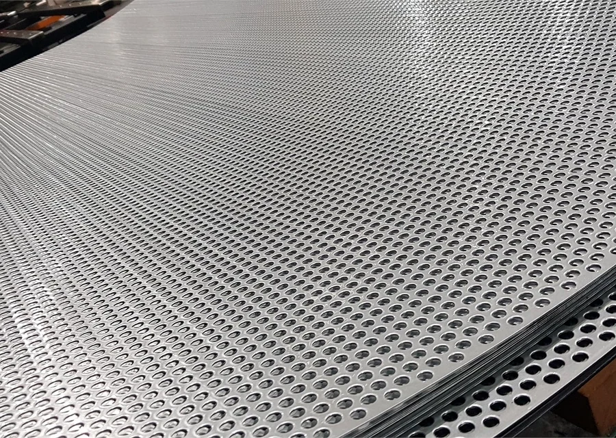
Confirm hole shape, pitch, open area, sheet size and finish when preparing perforated metal drawings.
What buyers should define before quotation
| Hole shape | Round, square, slot or custom hole pattern. |
|---|---|
| Hole size and pitch | Diameter or slot size, center distance, staggered or straight pattern. |
| Open area | Open area affects airflow, visibility, drainage, weight and strength. |
| Sheet size | Overall sheet size, margin, blank border and cutting requirement. |
| Material and finish | Carbon steel, galvanized, stainless or aluminum with suitable finish. |
How to turn a hole pattern into a clear drawing
Specify the arrangement, not only the hole size
A hole diameter does not define the complete pattern. Mark whether round holes are on straight square centers or a 60° staggered triangular layout. Dimension center-to-center pitch rather than the clear gap between hole edges. If row spacing and column spacing differ, show both dimensions and the row offset. For slots, give width, overall end-to-end length, end shape and the slot direction relative to the long sheet edge. A small dimensioned pattern detail is clearer than a photograph without a scale.
Compare open area on the same basis
For round holes, let d be hole diameter and p the equal center-to-center pitch, using the same unit. The ideal patterned-field open area is 78.54 × (d/p)² percent for straight square centers, or 90.69 × (d/p)² percent for a 60° staggered triangular pattern. These formulas do not describe a 45° pattern, unequal rectangular pitches or slots. Do not select a pattern from open-area percentage alone: two layouts can have different hole sizes and clearances despite similar percentages.
Separate the perforated field from the sheet outline
Show the overall length, width and thickness separately from the perforated rectangle. Dimension each of the four unperforated margins from a named edge; do not assume every border is equal. Mark cutouts, mounting holes, bend lines and any blank strips around fixing points. State whether edge holes may be cut through or a complete unperforated border is required. Check which way the pattern must face when adjoining panels are installed together.
Confirm the drawing before comparing quotations
Send the drawing revision, material grade, thickness, sheet count, pattern dimensions, margins, finishing sequence and delivery destination in one RFQ. Identify the visible face and ask how burrs, cut edges and flatness will be agreed. If a dimension must be checked after coating or forming, say so explicitly instead of assuming a finished-hole tolerance. Ask the supplier to identify any proposed change to pitch, border or panel size; an alternative should not silently replace the requested geometry.
Geometry example — not a stock specification
For d = 5 mm and p = 8 mm, the layout alone changes the calculated open area:
| Straight square centers | 78.54 × (5/8)² ≈ 30.68% |
|---|---|
| 60° staggered triangular layout | 90.69 × (5/8)² ≈ 35.43% |
These are rounded geometric examples for the patterned field, excluding blank borders and cutouts. They are not load capacities, pressure-drop predictions, manufacturing limits or a promise of available stock. Whole-panel free area depends on the actual perforated region; service performance needs a separate project review.
Send drawings, sizes, material, finish, quantity and destination. QY Metal Tech will review the details and reply with practical quotation support.
Send Project RFQRelated product pages
Use these product pages together with the guide when preparing drawings or a quantity list.
Product and RFQ path
Use this guide to move into the right product page
After defining hole pattern and sheet details, continue to related mesh product paths or send a drawing-based inquiry.


